Many of the applications of Photon Systems deep UV lasers involved detection of radiation emitted from target materials resulting from excitation by our lasers. Excitation in the deep UV typically generates a wide range of optical responses from target materials including Rayleigh (elastic) scattering, Raman scattering, photoluminescence, fluorescence, or phosphorescence. Photon Systems lasers and plug-and-play digital detection controllers offer an easy to use and high signal-to-noise method of measuring weak signals resulting from deep UV laser excitation. This brief discussion describes the methods of detection available from Photon Systems.
CW versus pulsed UV lasers
Very few lasers with emission wavelengths in the UV operate in continuous wave (CW) mode. These include helium-cadmium lasers (HeCd) operating at 325 nm, and frequency doubled FreD argon or krypton lasers. Typically CW HeCd lasers emit from a few mW to about 20mW at 325 nm and FreD argon lasers emit 5 mW to over 100 mW at wavelengths ranging from 229 nm to 364 nm. He-Cd lasers typically are relatively small, consume less than 300W, and are air-cooled. FreD lasers are typically relatively large, consume over 10kW of power, and require water-cooling.
All other lasers operating in the UV are pulsed lasers including: a variety of 3rd, 4th, and 5th harmonic solid state lasers emitting at 355 nm, 266 nm, and 213 nm; nitrogen lasers emitting at 337 nm; and hollow cathode HeAg lasers emitting at 224.3 nm and NeCu laser emitting at 248.6 nm. Harmonic generated solid-state lasers typically emit pulses with pulse width less than 10 ns and often less than 1 ns. Because of the narrow pulse width solid-state lasers often cause thermal damage to samples under test, since the laser energy is deposited before the resulting heat can be conducted away from the focused laser spot. Hollow cathode lasers emit pulses with pulse width adjustable from about 10 ms to over 300 ms. Because of the long pulse width, these lasers typically do not cause thermal damage of target materials.
Control and measurement of outgoing laser energy
Built into each Photon Systems deep UV laser is a laser output detector that senses the output of the laser for each laser pulse. Outgoing laser pulse information is displayed in the form of digital oscilloscope waveforms as well as a bar graph showing total integrated pulse energy for each laser output pulse. This information is available in digital form to enable normalization of information obtained from target samples being excited by the laser.
The laser output power, pulse width, pulse shape, and pulse repetition rate are computer controllable as stand alone lasers or in conjunction with instruments in which they are imbedded. Typically Photon Systems deep UV lasers emit several tens to hundreds of milliwatts during a pulse with a corresponding pulse energy ranging from a few microjoules to about 50 microjoules. Control software is via LabView graphical user interface.
Digital detector controller
The combination of Photon Systems deep UV laser and digital detection controllers provides a powerful method of detecting weak signals resulting from excitation of targets in the deep UV. In order to obtain the highest signal to noise (S/N) from a signal in the presence of significant noise and interference, detection usually employs some form of phase locked detection or integration method. Detection of weak signals from a sample using CW laser excitation typically utilizes a lock-in amplifier in conjunction with a chopper which chops the CW laser excitation or emitted energy into an on/off square wave prior to detection. Since the signal is proportional to the CW excitation power of the laser, detection is typically not as sensitive as with pulsed lasers. Detection of weak signals from a sample using pulsed laser excitation typically utilizes a gated boxcar integrator and averager to synchronize detection with the laser pulse and integrate signals only when the gate is open, ignoring noise and interference that may be present during other times. This method offers much of the same advantage of a lock-in amplifier combined with the advantage of a much higher signal strength since our pulsed lasers provide much higher deep UV output than typical CW deep UV laser.

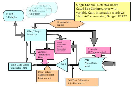
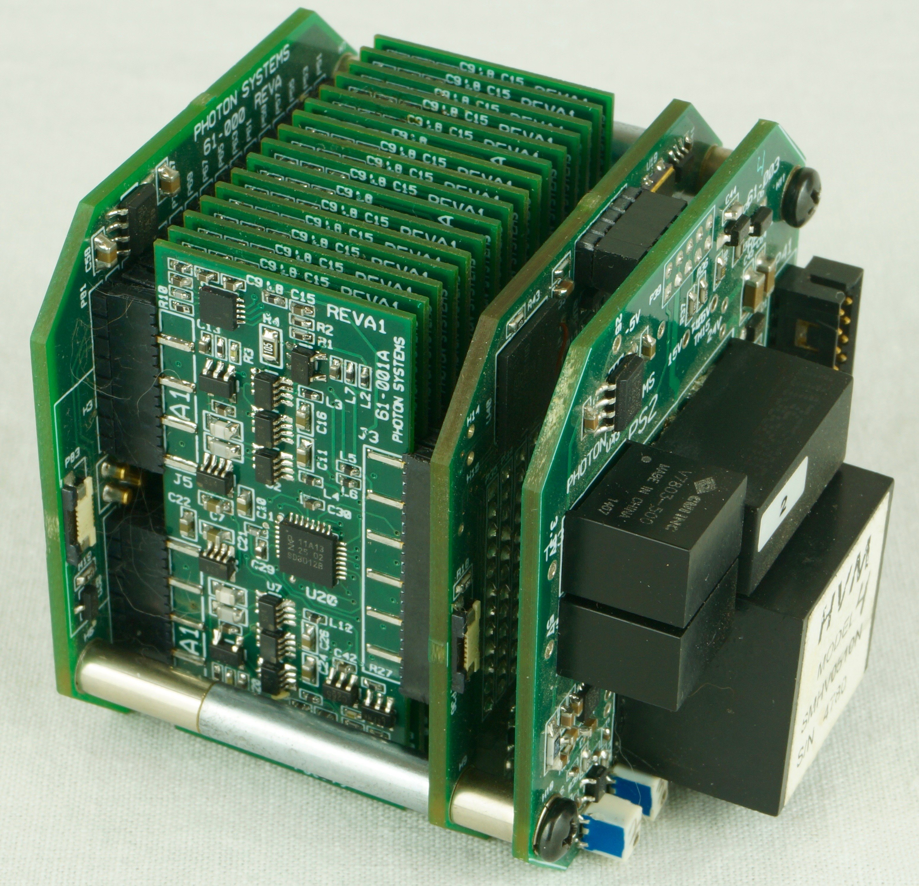
Photon Systems manufactures a unique digital detector controller (DDC) which combines a PMT gain controller with a gated boxcar integrator and averager that is a plug-and-play module that plugs directly into the rear of any of our deep UV lasers to enable ultra-sensitive gated integration of signals only during the period when the laser is “on”. Unique to our DDC design is the ability to computer-select any one of four (4) integration capacitors, 47 pf, 470 pf, 4700 pf and .047uf. Each of these capacitors can be calibrated using a precise internal standard to determine the exact value of each capacitor rather than rely on the “nominal” values listed above. This capacitance accuracy along with a measured absolute PMT gain as a function of control voltage, QE of the Photocathode, and well voltage of the A-D, is employed in our DDC to determine the actual number of photons detected during the gate time. Beginning and ending integration times for detection is computer selectable to coincide with the laser pulse width selected. Normally, the gate period is chosen to coincide with the laser pulse, but if the sample has significant phosphorescence or long duration fluorescence, the detection gate period can be selected to occur after the laser pulse.

The following describes details of the performance of the Photon Systems single channel Digital Detector Controller (DDC). Although originally designed for use with a photomultiplier tube (PMT) to control the PMT and sense and digitize the PMT output in synchronism with stimulation by one of our deep UV laser products, our DDC can be used for a wider range of applications of sensing very small electrical currents associated with optical beam induced current (OBIC), surface photovoltage spectroscopy (SPV), and other techniques. These applications and others are a logical extension of the use of our DDC.
The normal pulse duration of our 224nm HeAg lasers is 100us, but the pulse width can be adjusted out to perhaps 300us or so. The normal pulse duration of our 248nm NeCu laser is about 30us and can be extended out to perhaps 50us, but not effectively much longer. These lasers can be pulsed in single pulses or streams or bursts of pulses. In any case the DDC is gated in synchronism with our laser and does not require any other electronics. We normally use our DDC detection electronics with photomultiplier tubes to look at Rayleigh, Raman, photoluminescence, fluorescence, or phosphorescence emissions generated by our UV lasers. But the input to our DDC could also be used for OBIC, SPV and other, non-radiometric, applications.
The input impedance of our DDC is in the gig-ohm range, with minimum current measurement about 20pA (20E-12A). The PMT, which we normally use, is a current source so it is similar to the input source from other devices or detectors. The current source is inputted into an Analog Devices AD8618 op amp that is similar to JFET devices. The bias current is about 0.2pA, which can be offset. The smallest feedback (integration) capacitor for the op amp is 47pf. When one of our deep UV lasers is commanded to pulse, the selected integration capacitor is shorted to ensure no charge is on the capacitor at the beginning of the integration period. At the end of the integration or gate period, the capacitor voltage is digitized using a 16-bit analog to digital converter. The voltage resolution of the A/D converter is 38 mV/count, corresponding to 1.78E-15 coulombs, or 2966 electrons using the 47 pf integration capacitor. When operated at a PMT gain of 106, this corresponds to less than 1 photoelectron at the photocathode of the PMT. Typical dark current for the Hamamatsu H6780 PMT modules typically used with our DDC is 0.2 nA, corresponding to an anode photoelectron count during a 50 us laser pulse of 62,500 anode electrons or less than one cathode photoelectron. With a PMT quantum efficiency about 20%, in all cases our DDC should be capable of measuring signals as low as about 5 photons incident on the PMT photocathode.
Data Processing
Built into each Single channel detection controller is firmware intended to enhance real time processing of the digital data collected from either a PMT or Photodiode. Photon Systems generates a gain vs. control voltage Look Up Table (LUT) for each DDC board and PMT/Photodiode combination. In addition all the photon calculation parameters (Cap value, QE, etc.) enabling the incident photons calculation on the photocathode are stored in on-board memory for easy safe access.
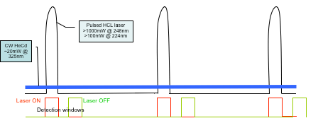
The Digital Detector Controller also has a significant amount of firmware on board. Referring to figure 1 notice that there are two sets of data collected for each laser pulse: one, during the laser pulse, for collection of data with laser excitation and a second, after the laser pulse, to collect background or ambient data with no laser excitation. Each collection uses the same collection parameters (gain, integration time and Cap value). This second data collection is without the laser pulse and is referred to as background or Quiescence value. It is saved along with the actual data set and may or may not (user selectable) be subtracted from the laser data producing a “background subtracted signal”. In addition to this feature, as mentioned above, the outgoing laser energy in each pulse is collected and saved. It is then divided into the data collected for that laser pulse. This produces a normalized data set that eliminates pulse to pulse variability as well as long term degradation of the laser or optics.
Automatic Gain Control is an added feature if desired. When the expected intensities of light to the PMT are varying during a run it is desirous to keep the detection electronics and PMT operating at the most sensitivity and best S/N. The integrating capacitor or PMT gain are automatically changed based on the known data in the PMT Look UP Gain Table. As the signal of the A-D reaches 90% the system will automatically adjust either the Gain or Cap insuring that the A-D output is in a range of 5000-50000 counts. This happens whether the output signal is increasing or decreasing always trying to keep the system at optimum. This process is performed in LabView, however all the control parameters are stored within the DDC module.

Get In Touch
Keep informed about the latest deep UV developments at Photon Systems by joining our mailing list.
ADDRESS
1512 Industrial Park St. Covina, CA 91722-3417
PHONE
626 967-6431
